# White Papers
An Engineer’s Guide to CRPA Testing

Executive Summary
This white paper will discuss the applications and use cases for CRPAs (Controlled Reception Pattern Antennas), how they work and the methods for testing them. It will also explore the various types of testing solutions available in the marketplace today, and help you choose the right solution for your specific application.
WHO SHOULD READ THIS WHITE PAPER
- GNSSGlobal navigation satellite system (GNSS): A general term describing any satellite constellation that provides positioning, navigation, and timing (PNT) services on a global or regional basis. See also/RF Test Engineers
- GNSS/RF Systems Engineers
- PNTPosition, Navigation, and Timing: PNT and map data combine to create the GPS service. Engineers
- Navigation Engineers
- NAVWARNavigational Warfare See also Engineers
- Signal Processing Engineers
- Avionics Engineers
- Program Managers
Introduction
CRPAs are becoming increasingly common, particularly in the Defense sector. CRPAs are an extremely effective anti-jam/spoof solution, because they adapt dynamically in response to jamming or spoofing signals. It is important to know the direction from which the interference is coming, so that you do not receive that RF power into your GPSGlobal Positioning System is a navigation satellite system. See also receiver. This is done by forming nulls in the direction of the interference, or by using beam forming techniques to isolate and track only the true satellite signals, ignoring the others.
When considering using any new device, it is important to test it prior to fielding − especially in applications like defense, where the stakes are high. It is absolutely critical to test these devices rigorously with a proper system that can achieve those testing capabilities.
Testing Antennas with a Simulator: Use Cases
When discussing simulation and GNSS simulators, it is important to choose the correct simulator for the platform that’s being tested. Most use cases begin with a single vehicle. This is an excellent starting point for how you should think about various types of simulation. Beyond that, you have multi-vehicle, then multi-antenna use cases, which are not as common. The most complex is the multi-element use case, which is typically associated with CRPA.

Figure 1
Single Vehicle Use Cases
Single vehicle use cases typically involve single antenna GPS receivers, and there are billions of these devices in the marketplace. These include FRPA (Fixed Radiation Pattern Antenna), simple patch antennas or other normal antennas. This is by far the most common simulation use case, and a good fit for a simulator such as Orolia’s GSG-5/6 essential simulators or GSG-8 advanced simulator – or for encrypted usage, Orolia Defense & Security’s (ODS) BroadSim.
Multi-Vehicle Use Cases
The next level up would be a multi-vehicle simulator. These are useful for RTK-based rover setups or drone swarms, as seen in Figure 1. An appropriate use case might be for two vehicles that need to dock or drive together and then part ways. This is not a particularly common use case, but it does happen. In this case, you would need to have multiple simulators. An anechoic chamber would not be appropriate due to the nature of the simulation.
Multi-Antenna Use Cases
A similar use case − not to be confused with multi-vehicle − would be multi-antenna. This is when you have more than one GPS antenna installed on a platform. For example, consider a precision agriculture tractor setup, as seen in Figure 1. There are two separate antennas, but they are just normal patch antennas.
These devices are used for more accurate heading and roll, and are typically found on construction or agricultural equipment. Again, this is not a very common use case and it does require multiple simulators. Because the antennas are in two separate locations, they are not compatible with anechoic chambers.
Multi-Element Use Cases: CRPA Antennas
Multi-element antennas are typically referred to as CRPA antennas. In these use cases, you are usually looking at anti-jam, direction-finding and/or angle of arrival.
These antennas are becoming more common in the defense arena and are expected to become more common in the commercial sector. They are compatible for anechoic chambers; however, a wavefront system is more appropriate to fully support this specific use case.
Controlled Reception Pattern Antennas
So, what is a CRPA? The acronym stands for Controlled Reception Pattern Antenna. Depicted in Figure 2, CRPAs are designed to reduce the effects of RF interference or establish signals’ angle of arrival. Using multiple antenna elements, they minimize jamming signals, using null generation or null steering or maximize “truth” signals using beam forming or beam steering. They are the best defense against jamming and spoofing threats.

Figure 2
CRPAs are a very useful antenna system for platforms that need to operate in environments where jamming and interference are commonly present.
There are other use cases for similar antennas, such as angle of arrival or direction-finding applications. They are not just for anti-jamming, although that is probably the most common example of a CRPA test.
What is a CRPA comprised of? It starts with some sort of multi-element antenna. In this example, Figure 3 shows a four-element antenna. There are four separate RF spigots coming off the bottom of this antenna, that would then be directly connected to the antenna electronics unit.

Figure 3
There’s nothing particularly unusual happening in the antenna itself − it really is just four separate antennas in a single enclosure. The real magic happens within the antenna electronics, where the RF then proceeds downstream to the GPS receiver. Often, you’ll see this sold as a solution that can be installed into existing platforms to protect existing receivers. You need all of these pieces to form a CRPA system, and this impacts how you go about testing.

Figure 4
There are other styles of CRPAs available. Single-enclosure antennas are sometimes called “integrated CRPAs,” where the multi-element antenna and the antenna electronics are in a single enclosure. Fundamentally, they work the same way, but it is not as obvious to the user that there are multiple cables involved, because the bottom only has one RF spigot. It is important to think about the differences in your approach to testing because it will affect how your test is physically constructed.
Methods of Testing CRPA
There are several test methods for testing CRPA antennas. You should evaluate these methods, their costs and suitability for the use case to ensure that your program needs are fully met.

Figure 5
Record Replay – It is realistic because it is actual recorded data – not simulated or generated. But once you have that recording, you are unable to make any changes, so you are stuck with that test case. You also need to find a suitable environment in which to record. This can be especially difficult, for example, if you want to record threats. You need to go where threats are in order to record them.
GNSS Simulator – This method is the lowest cost option. Industry has only been able to say that for the past couple of years due to advances in technology. Previously, simulation testing for CRPAs required very expensive and complex phase matrix equipment. If you have ever considered a wavefront simulator in the past but found it to be too costly or too complicated, it is worth taking another look, because innovation now allows us to do some cool things. Simulation also provides the flexibility to cover multiple test cases quickly, and it is conducive to fast iteration speeds.
Anechoic Chamber – This entails having a complete anechoic chamber system, which includes the simulation equipment and an actual physical chamber. It is very expensive and high in effort. You must consider all the variables, such as physical limitations and building standards for where you want to put the chamber. There are also several potential unknowns that you may run into during installation, which can mean more effort and more cost.
Field Testing – This is where you bring your device out in the field and attempt to replicate real-world scenarios by staging an environment and generating a threat. This method is often preferred because it facilitates tangible conditions, but costs can add up here as well. The event must be staffed, and licenses for each threat must be obtained per local regulations. As an attendee, you have no control over what or how threats are being generated. With limited access to the threats, you will not be able to cover all the possible test cases.
Ultimately, it is probably best to test by combining some of these methods. For complete system testing, you can start with GNSS simulators for fast iterations, then rent space in a chamber or attend a field test event.
Testing CRPA in an Anechoic Chamber
As mentioned, one way to test a CRPA antenna or entire system is with an anechoic chamber. Shown in Figure 6, the simulator system funnels the RF signals into the transmitters inside the chamber. Those signals are radiated to the multi-element antenna, the antenna electronics and the GPS receiver.

Figure 6
This is a very straightforward use case because it takes the entire system as it would be installed, places it into the chamber, then tests it that way. The nature of the simulation is preserved by using real, spatially separated signals, so that the CRPA receives the signals it should see. The accuracy of the angle of arrival of any signal is limited by the number of antennas installed in the chamber. Whether it is an integrated or a separate CRPA system, all the components get placed in the chamber.
Testing Typical and Integrated CRPA with Wavefront
When you’re testing with a simulator that is not radiating, unlike an anechoic chamber, you need to do a direct inject – sometimes called a conducted test – where you physically connect the RF cables to the device under test.

Figure 7
It is important to note that the antenna itself is not part of the test, so you would work with only the antenna electronics and the GPS receiver. However, since the instrumentality of a CRPA lies in the antenna electronics, it is still a very good way to test the CRPA’s reaction to threats and the environment surrounding it.
So, what do you do in the case of an integrated or a single enclosure CRPA? How do you use a simulator to test it? Some people assume that you cannot do it – but you can! However, it typically requires some cooperation with the manufacturer.

Figure 8
Basically, what must happen is to remove the top of the enclosure to access the RF connectors inside and attach the cables directly, as portrayed in Figure 8. Thus, you leave out the multi-element antenna, and the simulator outputs are connected directly to the antenna electronics. After you have physically made these connections, the test can proceed as normal.
Pros and Cons of Anechoic and Wavefront Systems
Now that you understand the fundamentals of each system, taking a deeper look into some of their pros and conscan help you decide which option is better suited for your situation and needs.
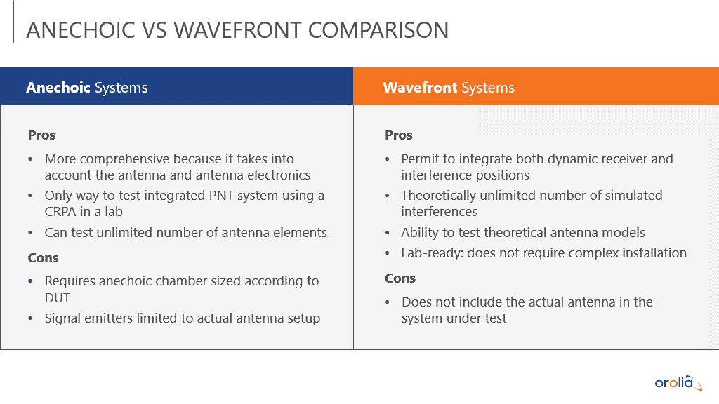
Figure 9
The anechoic, also known as “radiated method,” is the only way to test an entire system, because it allows testing of both the antenna and the antenna electronics. To phrase it another way, this would be the case if you wanted to test the antenna and the antenna electronics integrated as-is in a single package. Still, it requires that the chamber be an optimal size to accommodate the device or system under test. Additionally, you could be limited by the antenna setup in the chamber. All of this can significantly impact the chamber itself as well as the simulation, both in terms of accuracy and how realistic it can be.
For the wavefront, also known as “conducted method,” you are prioritizing the ability to have dynamic trajectories for the receiver and for the interference transmitter. That lets you do a great deal of testing. In essence, you can model virtually any scenario with an unlimited number of interferences. There’s no complex installation involved with this method. Unlike anechoic, a wavefront system is packaged lab-ready. Although you are not testing the antenna, the important part to test is the antenna electronics, so it is still a very good solution for testing CRPAs.
What Is a Wavefront?
Think about what happens when a signal from outer space arrives at an antenna location. Since it is a far away source, it shows up as a flat wave as it comes across and hits the antenna. Depending on the angle of arrival, it is going to hit different elements at different times.
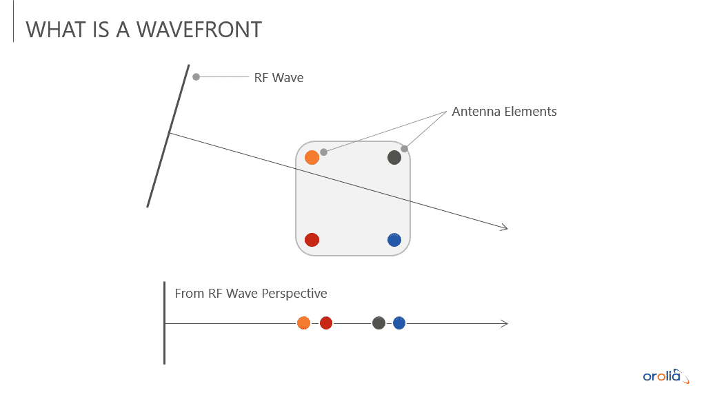
Figure 10
Represented in the figure directly above is a four-element antenna. From the point of view of the RF wave, if you imagine it sliding in the direction of the arrow, the first element that gets hit is orange, then red, then green and finally blue. The timing of the wave hitting these elements is very critical to achieve a valid simulation. Any small error would break down the signal environment in such a way that it would no longer be a valid test.

Figure 11
ften, we have multiple signals arriving in this manner, making this kind of simulation more intricate. These signals could be coming from satellites, jammers, spoofers, or some other origin. If you consider Figure 11 above, you can visualize the different RF waves intersecting and hitting the elements in a precise order at a precise time. Therefore, it is crucial to get the alignment just right when you are simulating this type of motion. If the alignment is off even slightly, you may hit the wrong element first, which causes problems in the math performed by the CRPA. Mutually, the timing and the arrival of RF signals is equally significant. Any error in the alignment and you have destroyed the simulation.
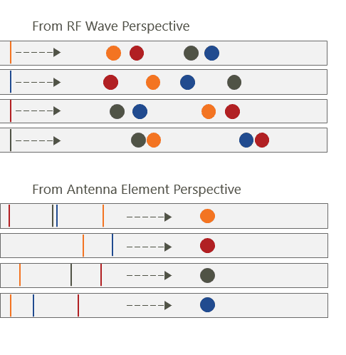
Figure 12
Creating the Wavefront Simulation
Now that you have visualized how the wavefront propagates to each element, how do you go about creating the simulation and streaming it? Orolia takes a software-defined approach. Starting off with modeling and simulation, you create the vehicle trajectory, the antenna pattern, the satellites, and add any jammers or spoofers. All that information is contained within the simulation software. Then, the software determines what digital IQ data must be generated to create the simulation, which is generated inside of high-performance GPUs. The digital data from the GPU then must be streamed to the phase-aligned software-defined radios. Each radio corresponds to a specific antenna element and generates an RF signal that gets passed to the antenna electronics.
As long as the phase alignment of the RF signal is preserved, the signals and data presented to the antenna electronics are correct and correspond to the simulation, so, the CRPA can perform the necessary math for a valid, accurate solution.

Figure 13
Wavefront Demonstration
In the demonstration previewed in Figure 14, a four element wavefront simulator is directly connected through four RF cables to a device called Northstar, by UHU Technologies. The device is not unlike a CRPA in that it has a four-element input. But instead of processing anti-jam, it computes angle of arrival by looking at interferometry in the C/A code. This is a very special technique that is relatively new, but it is a great way of showing visually what is happening in the simulated environment.

Figure 14
Above, on the left is the simulator and on the right is the web UI of the device under test (the Northstar). On the right is the sky map of the locations of all the satellites. The blue dots represent the locations based on the broadcast data from the satellite, which is where the satellites should be. The green dots represent the location that the satellite appears to be coming from based on the angle of arrival, as determined by the four-element array on the Northstar.
When the test starts to run, the green dots and the blue dots start off in the same location, with some minor variance, which is normal, although others are spot on. This indicates that the simulator is executing properly. At the beginning of the test, a spoofer is transmitting signals. The Northstar first detects power coming from the Southeast and displays it as a jammer.
But then, shortly after the signals are turned on in the simulation, all the green dots move to the Southeast on the horizon (Figure 15). Why does this occur? To put it plainly, the spoofer takes over. So, the angle of arrival of all these signals is now coming from the spoofer location, instead of from outer space where they should be.

Figure 15
This shows that the simulator is able to simulate multiple signals, true or spoofed, and that the spoofed signals do in fact have the correct characteristics to come from the correct location. In this example, there is a simple spoofer flying in a circle around a location. As that circle is flown, the location of the spoofed signals should appear to move over time (Figure 16).

Figure 16
You can see that as the spoofer moves, the apparent angle of arrival of all the spoofed signals also moves. As the simulation keeps running, it continues to form the circle as the green dots continue to come from the spoofed location. Watch YouTube video for a demonstration.
Skydel Technology
What does it mean to have a software-defined architecture? Orolia’s Skydel is a real-time simulation software that runs on Linux or Windows. To generate GNSS signals, it requires a GPU that is used as a co-processor, and a software defined radio to convert the IQ data into RF. Orolia selects high-end COTS (Commercial-Off-The-Shelf) hardware to create turnkey systems, but it is possible to run Skydel on your own hardware. Because it is not as dependent on the hardware, the architecture allows you to scale down to meet simple requirements or scale up to test more complex applications like CRPA.
Testing CRPA with Skydel
As explained previously, the two main methods for testing CRPA are anechoic and wavefront. In Figure 17, the anechoic chamber is connected to multiple antennas inside. Note that it is not always one antenna per satellite. It can be multiple satellites transmitting through the same antenna if they come from the same region in the sky. The closer they are in the sky, the more likely that they will be transmitted from the same antenna.

Figure 17
Orolia has a special tool that calibrates the system for a specific point inside the chamber, which is perfectly suited to testing CRPA because the antenna elements are very close together. So, the anechoic chamber and the simulation system are calibrated to have the correct time of arrival and power for the specific spot in the chamber where your device under test (the CRPA) is placed. Interference can be integrated with Skydel software or an external generator.
With the wavefront method, all signals for each element are brought to the antenna electronics via cables. The Orolia wavefront system is scalable from two to 16 elements, is phase coherent, performs real-time automated phase synchronization, and has built-in jamming and spoofing.
Scalable Architecture (Wavefront)
Illustrated in Figure 18 is the system architecture, which can scale up and down depending on the number of elements and signals, and dictates the number of GPUs, computers, and so forth. The diagram below shows how this works with an Orolia wavefront simulator.

Figure 18
The architecture starts with having simulator nodes. Each node corresponds to an element of the CRPA that is dedicated to simulating all the signals for that specific element. If you were to have a seven-element CRPA, you would use seven nodes to accomplish the simulation. Each node simulates the low power GNSS or “truth” signals, as well as the high-power signals such as jammers and spoofers. There are two different RF paths, which allow you to manage a huge dynamic range in power. Then the proper signals are sent to the RF distribution module at the bottom, where they are combined and brought to a specific element. The RF distribution module also provides a feedback loop to the simulator controller.
The simulator controller is the heart of the system. It controls all the nodes, coordinates them, synchronizes them, and sends commands to simulate the proper phase alignment and dynamics. It monitors the combined signal that feeds back to the controller. This allows the controller to measure the phase, compensate and make corrections, all in real-time, to ensure that the phase stays within the specifications of the system. Because this is done continuously during the entire simulation, you can be sure that you stay within specifications regardless of the duration of the simulation.
The simulator controller is also the single point of user interface. All the complex calculations and sequences are happening under the hood so you can concentrate on what you need to test: defining the scenario, the jammers, spoofers, and so forth. Thanks to the automation, you won’t waste any time waiting around. In seconds, special algorithms will compute the phase difference between each pair of elements. In less than a minute, your entire system will be calibrated and ready to go.
Built-in Jamming and Spoofing (Wavefront)
When evaluating wavefront simulators, consider whether it will help you test the limits of the device. An important characteristic of a good wavefront simulator is its ability to simulate threats – such as jamming, spoofing and repeating– in addition to GNSS signals. This is key, because CRPAs are designed to be resilient in very harsh conditions.
If you have a seven-plus element CRPA, you will need to simulate many jammers and spoofers before you reach its limit. You must be sure that your simulator can handle this volume of activity easily right from the outset. This capacity is built into Orolia’s wavefront system. Better yet, the GUI and API make it intuitive to automate everything with Python, C++, C-sharp, or whatever your preferred language.
You can add a transmitter at any location to broadcast a custom waveform such as an IQ file and you can combine multiple waveforms to create a robust signal environment. By moving your transmitter around, you can see how your device will behave from different directions. To take it a step further, you can layer in as many interferences as you want, gradually or all at once.
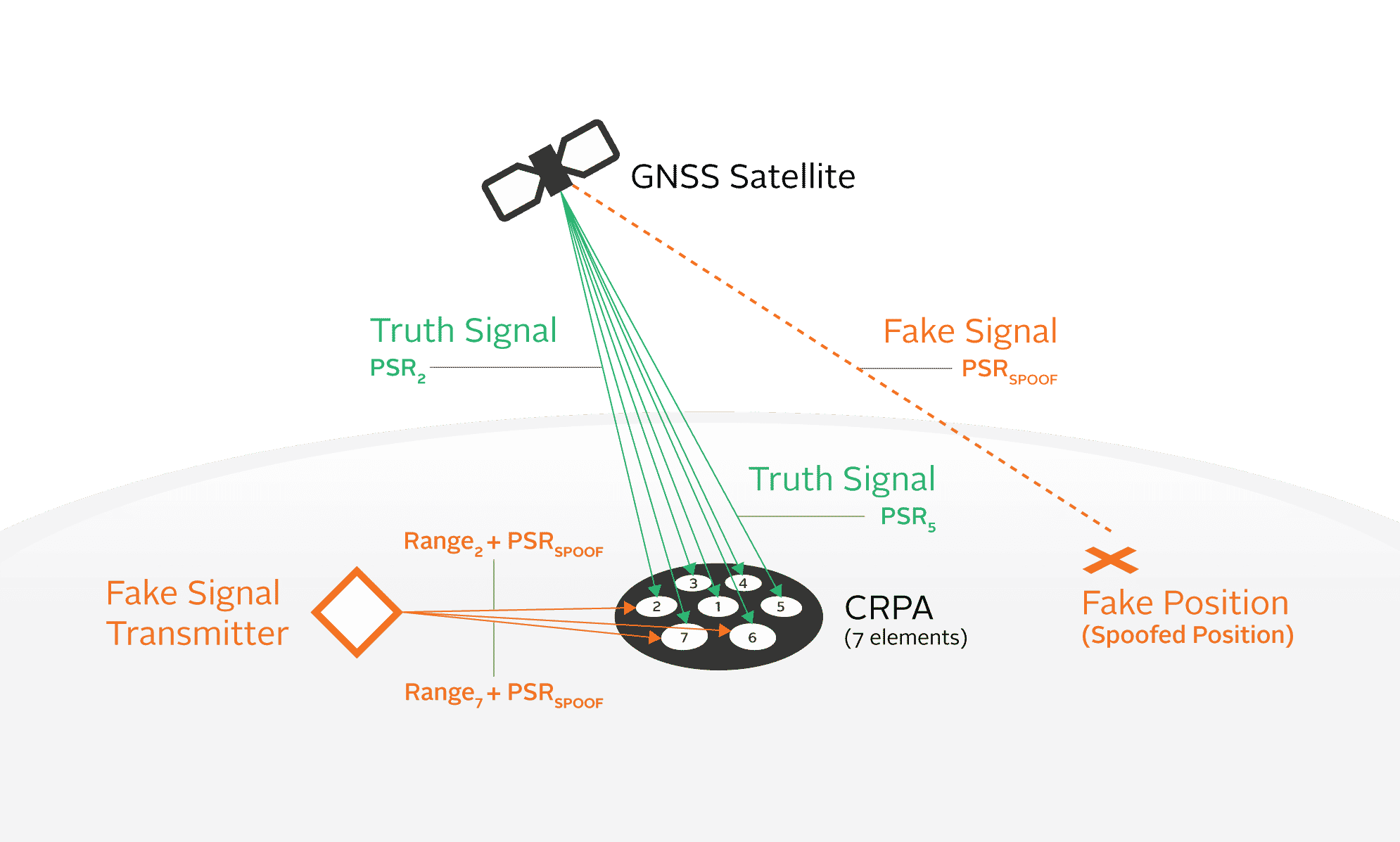
Figure 19
The actions you take to simulate a spoofer are like a jammer. You must define its location, movement, path, power level, and its transmitting antenna pattern because, for example, it could be beaming in one direction.
If you have already done all of this for a jamming simulation, for a spoofing simulation you simply select a different type of waveform to transmit. This way, instead of transmitting a basic waveform, it transmits the GNSS signals simulated by another instance of the Skydel simulation engine. Now you can have multiple instances connected, transmitting true and spoofed signals. The simulator takes care of all the dynamics, including added range for transmission, phase, doppler, etc.
All in all, just a few clicks will put a transmitter into space, relate another program instance as the spoofer trajectory and then start the simulation. In short, built-in jammers and spoofers make it easy to create very complex scenarios that were not possible even just a couple years ago.
Hardware (Wavefront)
All Orolia advanced simulators are based on a software-defined platform. This means that the simulator is not attached to a specific hardware design. The design never ages because the PC can always be upgraded with better GPUs and CPUs. Every time Intel or NVIDIA invests massive amounts of R&D to improve their hardware, that can be leveraged and integrated into this system, increasing the number of channels. It also makes the whole solution more economical to attain and maintain.
Many ask, “How many channels or signals can you simulate?” Orolia’s answer is “How many do you need?” because the system can be easily scaled to accommodate. The wavefront simulator shown below on the left holds seven boxes with a red LED strip on the front, and each box acts as one node per element for a seven-element CRPA. The inside of one node is pictured on the right.


Figure 20
One node can support over 1,000 signals using processing power gained from the GPUs and CPUs. Which begs the question – why would you need a thousand signals? Because, when you test a CRPA, the whole point is to reach the limit of what the CRPA can do.
If your device claims to be able to null a certain number of jammers, spoofers or repeaters, you need to be able to simulate them all in real-time. This requires a great deal of processing power because it actually simulates all the same things as truth signals. If you need 125 signals for the truth, and the same for each spoofer/repeater, and your CRPA claims to mitigate six spoofers/repeaters, you should probably consider testing with seven spoofers to extend beyond the CRPA limit. This scenario would require 1,000 signals per element, or 7,000 total signals.
Anechoic Integration Within Skydel
Now we’ll examine Orolia’s anechoic solution to test CRPA electronics. Instead of going about it by way of conducted signals, this method uses an anechoic chamber and transmits over-the-air (OTA). It is designed to speed up chamber calibration setup and reduce the multiplication of hardware systems.
In Skydel, an antenna transmitter can be programmed to transmit either GNSS signals or high-power jammers and spoofers. If some signals from different locations in space are close enough together, they will be associated and transmitted via the same antenna. In this way, with a limited number of transmit antennas – say 16, or 32 – you can capture the entire sky and have an unlimited number of satellites.

Figure 21
One very interesting feature that Orolia developed is the ability to auto-calibrate. To do so, you simply open a tool, place an antenna where your device under test is located, click a button, and voilà – the system automatically maps signals to the correct transmit chain, and calibrates the time delays and the power loss. Then, you can proceed to run your scenario knowing that everything is operating properly.
Looking specifically at the benefits of each Orolia solution with Skydel paints the big picture (Figure 22).

Figure 22
For anechoic, the antenna mapping, which is handled in the software, contributes to streamlined chamber setup. With wavefront,
you can have many interferences without additional licenses or hardware. Plus, the system optionally comes in a noise reducing rack to keep your lab quieter. The systems also share some benefits, including a compact form factor, seconds-long automatic calibration, higher performance, and ease-of-use.
There are also benefits to the Skydel Simulation Engine itself independent of each system. These include the powerful API and automation, intuitive user interface and cost effectiveness. Another advantage is its reliability to run longer tests with confidence.
Desirable Features of a Wavefront System
There are many small details that can have a big impact on the overall wavefront solution that you choose. When evaluating options, it is important to be aware of these details and ask the right questions.
Phase Alignment
With wavefront, it is not enough to synchronize the simulators with 10 MHz and 1PPS. The system must have a set of phase-stable or phase-matched cables, and the phase must be calibrated.
How often should the phase alignment be calibrated and checked when running the simulation?
Orolia’s wavefront system performs continuous calibration with real-time feedback, so outside of a systems annual calibration cycle, no additional calibration is needed. You will be able to instantly see the phase alignment.
How long does it take to calibrate the system prior to running a scenario?
Orolia’s wavefront system calibrates in minutes or less and ensures that the accuracy is maintained throughout the duration of the simulation.
Is there a time limit on how long a scenario can run and maintain the phase calibration?
Orolia’s wavefront system can run for an unlimited amount of time. If you leave for the weekend and come back, you should not have any doubts. Even so, you can go back and verify it.

Figure 23
Jamming and Spoofing
Anti-Jam Antenna Systems (AJAS) consisting of CRPA and antenna electronics that use nulling technology can create N-1 nulls, where N is the number of elements in the system. For example, a seven-element system can theoretically create six nulls.
Given that, any simulation system used to test AJAS systems must be able to simulate enough jammers and spoofers to reach the limitations of the DUT.
How do you configure jammers and spoofers in the system?
Orolia’s wavefront system takes advantage of the advanced jamming and spoofing capabilities of the Skydel simulation engine. It is easy to configure jamming and spoofing signals from the GUI, as part of the integrated system.
How many jammers can you have on a wavefront system? How many spoofers?
Literally hundreds if desired. The number of spoofers is only limited by the system license, and you can add more processing power wherever needed to generate additional signals.
What J/S (jammer-to-signal) ratio is achievable with a wavefront system?
Orolia’s wavefront system can simulate jammers with a maximum output power at -10dBm, which will give you a J/S of about 120dB. When testing anything, especially CRPA, it is important to have a high J/S so you can push the device to its limits and see what happens.
System Scalability and Upgrades
As technology advances, so does the threat of intentional and unintentional jamming and spoofing. AJAS will evolve as well, adding new capabilities, increasing the number of elements, and supported GNSS frequency bands and signals. A wavefront system is a large investment and should be as future-proof as possible.
What if you want to add additional signals to the wavefront simulation? Do you need to purchase additional channels? Is it a hardware or a software upgrade?
Orolia’s wavefront system is not limited to hardware channels; it can always generate all-in-view signals for any constellation. Adding additional signal support is typically a software upgrade. In some instances you may need extra processing power in the form of GPUs, or SDRs may be added to the system if you are adding new frequency bands or signals that need additional RF. But there should not be any major overhauls. This scalability allows the system to expand to meet future known and unknown needs.
What if you want to add more spoofers?
Spoofers are considered the same as adding additional signals to Orolia’s wavefront system.
As a system grows, will you make any performance compromises at any point?
Let’s say that you already have a system and you want to double its size. With Orolia’s wavefront system, the specifications will remain the same, regardless of how large the system gets. You can purchase a system with the number of elements you need today and increase the number of elements later. Most other aspects are a part of the software.
Encrypted Signals
Do you need encrypted signals?
If you have a secure application, which is generally true with CRPAs, it is recommended to test with encrypted signals. Orolia Defense & Security’s BroadSim Wavefront fully supports P(Y)-Code, AES and MNSA M-Code.
Antenna Element Radiation
Does the system have a way to account for the antenna element radiation pattern?
The same engine (Skydel) powers both the Orolia wavefront and anechoic systems. For wavefront, it combines multiple antenna patterns. In the GUI, you define the physical location of the antenna elements, choose an antenna pattern for each element (they can be different), orient the antenna the way you want, and adjust the gain or phase offset based on the elevation. This flexibility allows you to reproduce the pattern of an existing CRPA – or you can create your own experimental patterns.
Conclusion
Proper CRPA testing is complex and a large investment. A wavefront simulation system is the lowest-cost option when you consider all the variables. Before committing to a purchase, you want to be aware of any limitations in the system in advance and when adding more functionality, signals, jammers and spoofers.
Be sure the system is scalable for future needs – inquire now about future capabilities and costs.
Today, you really can say goodbye to expensive, rigid, limited solutions. Orolia’s CRPA testing systems are more capable than ever, easy to use, and enable repeatable tests. You do not have to be an expert in order to use them, and they can simulate threats that are difficult to reproduce, even in field testing.
If you are curious about investing in a CRPA testing system, Orolia will help you make the right move. For more information, contact sales@orolia.com.
If you have a need for GPS encrypted signals, contact sales@oroliads.com.
Tim Erbes
Director of Engineering, Orolia Defense & Security
Stephane Hamel
Previous Chief Innovation Officer, Orolia
Lisa Perdue
Product Line Director – Simulation, Orolia
