How to Test the Resilience of Your GNSS Receiver to the Ligado Network

If you have read the Ligado white paper by my colleague John Fischer, you now understand the challenges caused by the new Ligado signals. This communication network will broadcast signals in the near L1 Band, potentially interfering with GNSSGlobal navigation satellite system (GNSS): A general term describing any satellite constellation that provides positioning, navigation, and timing (PNT) services on a global or regional basis. See also signals.
Even with this power reduction, the Ligado signals are not harmless when approaching a station. Manufacturers and integrators of GNSS receivers should assess these effects on their own receivers. Be aware that this study, which was done in the WSMR (White Sands Missile Range) facility, has been conducted using testing means not available to most of the public.
This blog will show you how to evaluate the resilience and performance of your receivers in such environments with accessible equipment.
Conducted or Radiated
The best way to test the effects of interferences on GNSS receivers in a controlled, reproducible way is to use a GNSS simulator. The simulator can be used whether for conducted or radiated testing.
Conducted tests are relatively easy to set up and affordable. However, they yield a worst-case result (especially for jammers far from the GNSS band), because any beneficial filtering effects from the antenna are not included. Where possible, you can include the embedded LNA (low noise amplifier) in the tested device that will approach the actual setup. If the out-of-band rejection of the antenna is known, it can also be considered in the simulation by decreasing the power of the interferences.
To include the antenna in the tested setup, radiated tests are required. The receiving antenna is placed inside an anechoic chamber while the simulator’s transmitting antenna(s) broadcasts GNSS and interference signals. Fine calibration is required to reach the correct signal power at the receiving antenna location. Anti-jamming antennas like CRPA or GPSdome can also be part of the setup.
GNSS
The considered Ligado signals are in the 1475 to 1675 MHz range, left and right of the GNSS L1 Band. In theory, other GNSS bands (L2, L5, E6) should not be impacted, limiting the 1-dB criteria and the performance assessment to the L1 signals (GPSGlobal Positioning System is a navigation satellite system. See also C/A, L1C, Galileo E1, GLONASS L1, etc.).
However, for holistic testing, it is beneficial to include all GNSS signals supported by the receiver. Signals from other bands and constellations will help the receiver maintain accuracy, continuity and reliability, even when the L1 signal is deteriorated. Therefore, these aspects should be assessed in the testing plan.
Interferences
The DOT study identifies two types of interferences, 1 MHz AWGN and 10 MHz LTE signals (referred to as Type-1 and Type-2).
Type 1: The signal tested is bandpass AWGN with 1 MHz bandwidth. The Type 1 signal was selected for testing at all 22 frequencies to provide a narrowband signal for assessment of a general receiver mask not specifically tied to LTE.
Type 2: The signal emulated LTE characteristics representing both a downlink and an uplink. The downlink was emulated as a fully loaded base-station with Orthogonal Frequency Division Multiplexing (OFDM), and the uplink with Sub-Carrier OFDM (SC-OFDM). The LTE digital waveforms were generated using the MATLAB LTE package.
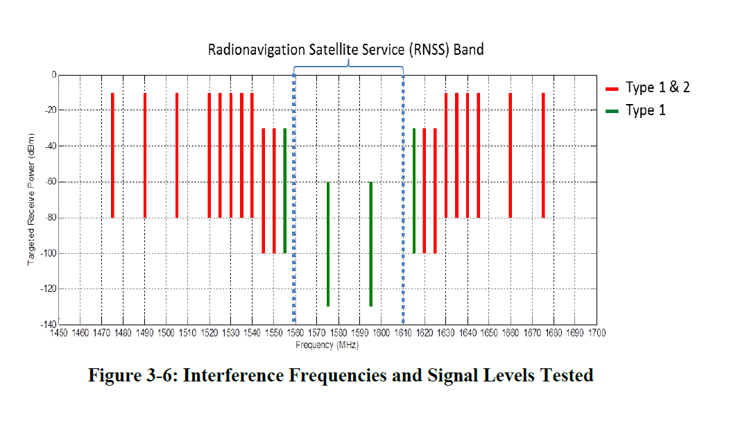
Source: US Dept. of Transportation GLOBAL POSITIONING SYSTEM (GPS) ADJACENT BAND COMPATIBILITY ASSESSMENT study.
For testing a receiver in a realistic environment, Type 2 interferences are more relevant. For a simplified testing campaign, only the 1550 MHz interference can be evaluated. It has a closer frequency to the L1 band, and consequently the strongest expected impact. For a full assessment, intermodulation effects between different frequencies should also be simulated.
Test Scenarios
Different and complementary testing approaches should be considered. First, the robustness of the receiver to the interference can be directly assessed by progressively increasing the power of the transmitter. To facilitate interpretation of the results, the satellite’s power should be set to a specific value (e.g. -130 dBm). The CNR of the receiver should be monitored and recorded, and the 1-dB threshold calculated from these data. This will provide the maximum interference power that the receiver can withstand before being impacted.
Second, set the transmitter power to a given value like 9 dBW and check the 1-dB criteria at different distances from the receiver. If the surrounding environment of the receiver is known or expected (for example, a base station every 500 m), its robustness can be evaluated with a realistic network of LTE transmitters.
Finally, the 1-dB criteria test is essential but insufficient to evaluate the actual behavior of the GNSS receiver. There are a multitude of receiver designs and algorithms, and all these will react differently to a 1-dB drop. Multi-frequencies, multi-constellations, tracking loop tuning, measurement smoothing, and PVT algorithms are some components of the receiver design that will change its resilience to different environments. We recommend that you assess the performance of the receiver based on quantifiable measurements such as time of acquisition, accuracy and integrity. In these tests, the simulation scenarios should be less idealistic, with realistic trajectories, satellite power, atmospheric delays, multipath, etc.
Orolia Solutions
The GSG-8 GNSS simulator meets all requirements for the conducted or radiated tests described here. Multi-constellations, multi-frequencies, and interferences (in the 32 – 2186 MHz band and with IQ playback) are all embedded in a single chassis in the GSG-8, offering a convenient solution. The user interface and API allow quick configuration of each scenario and seamless automatization. The GSG-8 supports all kind of dynamics, from a static receiver to space trajectories.
When the tested setup includes anti-jamming directional antennas like CRPA, the GSG-8 upgrades to BroadSim Anechoic or BroadSim Wavefront. All three of these advanced simulators are based on the underlying Skydel Simulation Engine (SSE). The Skydel Simulation Engine couples advanced performance with economy of scale and the flexibility of the GPU/SDR architecture.
Orolia is a leading expert in resilient PNTPosition, Navigation, and Timing: PNT and map data combine to create the GPS service., both for simulation and reception. We can support our customers in their projects and provide tailored solutions that are easy to use, affordable and fully featured.
