# White Papers
The Importance of Testing to Detect GNSS Vulnerabilities in Intelligent Transportation Systems
Introduction
For more than a decade, GPSGlobal Positioning System is a navigation satellite system. See also has been at the core of the navigation systems used in all types of road vehicles, train systems and marine transport vehicles. As industry moves from standalone navigation systems to the advanced multi-sensor systems used in intelligent transportation systems (ITS), GPS signals remain a key component of these systems.
At the same time, the availability of knowledge and equipment used to exploit and disrupt the GPS signals and service has increased to the level that anyone with a few dollars and access to the internet is able to fool or deny usage of the GPS system.
In addition to GPS, there are several other satellite constellations available globally. GLONASS is a Russian-controlled system, BeiDou is a Chinese-controlled system, and Galileo is a Europeancontrolled system. These systems (including GPS) are known as Global Navigation Satellite Systems (GNSSGlobal navigation satellite system (GNSS): A general term describing any satellite constellation that provides positioning, navigation, and timing (PNT) services on a global or regional basis. See also). Signals from these constellations are available for use around the world, and many receivers use two or more of them for navigation.
It may not be obvious to the user of a navigation system which of these constellations are in use, but it is important to know that their system might be using multiple constellations to provide a position.
GNSS Vulnerabilities
GNSS signals are vulnerable to interference, whether intentional or unintentional, due to their low power level and open interface specification. With a power level of approximately -130dBm in the open air, it does not take a lot of power to overpower GPS signals and cause GPS receivers to cease operation. This is known as a receiver being jammed. Jamming is only one of the potential ways to disrupt GPS receiver operation.
GNSS vulnerabilities are split into two categories: intentional and unintentional threats.
Unintentional threats are things that can occur but are not meant to cause any issues with GNSS performance and operation. GNSS system errors, unwanted RF transmissions and natural phenomena are all examples of unintentional threats to GNSS.
GNSS system errors can occur when bad data is transmitted by one or more satellites that cause an error in the receiver calculations.
Unwanted transmissions occur when a device transmitting a frequency at or near the GPS frequency of 1575.42MHz or a harmonic of this frequency causes interference of the actual GPS signals.
The same is true for the frequencies of the other constellations’ operating frequencies. Ionospheric scintillation is an example of a natural phenomenon that can cause GPS errors and even loss of GPS lock.
Intentional threats are either jamming or spoofing attacks. Jamming is transmitting a signal at the GNSS frequency at a high enough power level that it prevents the receiver from being able to lock to the GNSS signals. Spoofing is a deliberate attempt to deceive the GNSS receiver by broadcasting signals that the receiver will use instead of live sky signals.
Spoofing is different than jamming. Jamming is easier for a receiver to detect, and although it can disrupt the receiver, it cannot re-locate it.
Recently, a paper was released where researchers from Virginia Tech, University of Electronic Science and Technology of China, and Microsoft researchers described being able to spoof vehicles and cause drivers to follow the wrong route using $223 dollars’ worth of equipment. This happened with human drivers behind the wheel. This example emphasizes that spoofing is not only possible, it is inexpensive to do.
GNSS Performance Testing
The development of autonomous vehicles for road, rail and water demands a comprehensive and repeatable test plan for GNSS performance and vulnerability assessment. The test plan
development should be based on the application and the risks to the system. The GNSS system can be tested alone or as part of the larger system including other sensors.
GNSS performance testing includes these tests: Position accuracy, time to first fix (TTFF) and acquisition and tracking sensitivities.
- 1. Testing position accuracy includes providing a simulated signal to the device under test, and comparing the position outputs to the truth data provided by the simulator. Position accuracy tests can include stationary and moving trajectories, where the dynamic profiles match that of the vehicle the device is installed in.
- TTFF testing means testing how fast the navigation equipment can obtain a position fix after a cold, warm, or hot start. A cold start is typically performed by issuing a command to erase the stored position, date/time, almanac, and ephemeris data from a receiver.
A cold start is typically not performed when a receiver is powered off and powered back on. This is usually a warm start, which means the receiver keeps the position, date/time, and almanac. This allows the receiver to get a faster TTFF than it would with a cold start.
A hot start occurs when the receiver loses the signal for some amount of time but remains on. It keeps all the data it previously had and gets a position fix again in just a few seconds.
An example of a hot start is traveling through a tunnel. Measuring sensitivity is simply a matter of increasing or decreasing the power level until the receiver gains or loses lock.
For acquisition sensitivity, you can start with a low power level and increase the power
level until the receiver starts to track satellites and gets a position fix.
After a fix is obtained, the power level is lowered again to the point the receiver can no
longer report a valid output.
Once these baseline tests are done, and the results are recorded, it is time to start implementing environmental features such as signal fading, interference and multipath. Use simulation equipment to create these environments and redo the basic tests as described above. It is then possible to determine how much of an impact these environmental factors would have on position accuracy, time to first fix and receiver sensitivity.
Testing for GNSS Vulnerabilities
You could assume that the use of multi-GNSS receivers, sensors such as Lidar and Radar, and cameras will protect the vehicle from falling prey to a GPS spoofing attack. But that assumption would be wrong. The only way to understand how a particular receiver or system will react to a spoofing or jamming attack is to test it.
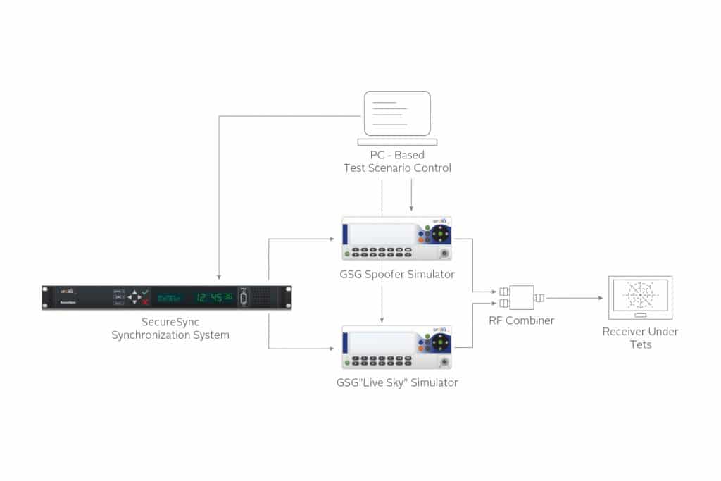
To test the reaction of a system to jamming and spoofing, a GNSS vulnerability test system can be used. Such a system is shown below.

The system uses two GNSS simulators and a device to synchronize them. The first GNSS simulator represents the live sky environment and the second simulator represents the threat (interference, jamming, or spoofing).
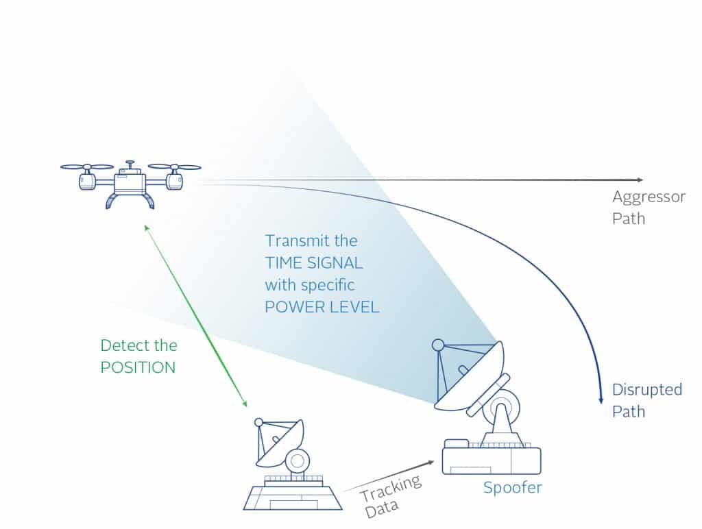
There are several parameters that can be varied to help understand how vulnerable a specific receiver is to the spoofing threat. Each of these parameters can vary independently of the other parameters, allowing design of a comprehensive test plan. These parameters are: Time, Position, and Power level.

Time. This refers to the timing accuracy of the spoofing signals to the live signals. There are commands available in the test system to start the spoofing signals with an offset, either fixed or moving, to determine how accurate the spoofing signals need to be in time to successfully spoof the system.
Another time to consider in the test design is the capture time. This is how long the spoofing
signal is applied before attempting to re-direct the receiver.
Position. The position provided by the spoofer must be accurate to that of the receiver to be spoofed. Exactly how close the spoofer must be to the receiver position is a variable parameter and can be different based on receiver settings, receiver manufacturer and initial conditions (moving vs. stationary).
Using two simulators allows full control of the two positions so that many different test cases can be designed and executed to understand the receiver limitations. The more accurate the spoofer must be to successfully take control of the receiver, the more difficult it will be for an attacker to spoof the receiver.
Below is an example of the two different positions with a 500m offset.

500m Position Offset
Power. The spoofing signal should be greater than the live signal to capture the receiver. The spoofing test system allows full control of the power levels to determine how much greater the power should be. Too much power will jam the receiver. The test system allows testing of the receiver to try and determine if there are any indicators given by the receiver when a signal only a few dB higher than the transmitted signal is received.
Testing these variables will indicate how vulnerable the system is to a spoofing attack. For
example, if the position given by the spoofer must be with 1m of the actual position in order to spoof it, the receiver already has a chance of rejecting a spoofing attack. Same for the timing synchronization – if the time sync needs to be 10ns to spoof it, this is very hard to achieve and provides some protection. If an attacker is spoofing a moving vehicle, properly estimating the position when the spoofing signals will arrive at the antenna, and accounting for the time of flight, is more difficult to do the further away the spoofer is from the receiver under attack.
Conversely, if the time synchronization just needs to be to the nearest second, or the receiver will accept any position within 100km, the receiver is not very resilient and other measures should be taken to protect the system. This also allows the spoofer to be much further away and generate less accurate signals to achieve the system takeover.
Additional things to consider are use of multifrequency and multiconstellation receivers. Tests should be performed to determine whether a receiver operating with multiple constellations and/or multiple frequencies will follow the spoofer’s signals if those signals are GPS L1C/A. This will indicate how complex a spoofing device must be to effectively spoof the receiver.
When it is necessary to test the GNSS receiver along with the other sensors in the vehicle, the simulation equipment must be integrated into a larger system. The trajectory or path of motion information is typically fed into the GNSS simulators in real-time as other sensors in the vehicle are stimulated or simulated at the same time. An example of a GNSS simulator integrated with an automotive test solution is shown below.

Conclusion
Understanding how GNSS receivers perform in different environments and under different threat conditions is key to identify suboptimal conditions and mitigate their impact on the overall system. As long as a GNSS receiver is part of an automobile, train, or ship, a GNSS test plan should be designed and executed regularly to identify weaknesses in the system. Knowing these weaknesses allows system designers to take action before facing a potentially critical situation where a weakness is exposed during normal operation. GNSS simulators and Vulnerability Test Systems are important pieces of test equipment for the development of any intelligent transportation system and verification lab and should be used regularly to avoid failures in the field.


